TiAl intermetallic compounds can significantly improve material properties through deformation-induced phase transformations, but there is a lack of sufficient knowledge about the mechanism of plastic deformation of TiAl intermetallic compounds. In this paper, the dislocation slip and twinning deformation mechanisms of TiAl intermetallic compounds are investigated at the nanoscale using \(\gamma\)-TiAl and \(\alpha_{2} \text{-Ti}_{{\rm 3}} \text{Al}\) in the bicrystalline structure TiAl alloy. Using applied scanning electron microscopy (SEM) and electron backscatter diffraction to characterize and analyze the internal organization of the deformation, the slip energy barriers were calculated by Schmidt factor \(\mu\) analytical technique, and the twinning deformation mechanism of \(\gamma\)-TiAl and \(\alpha_{2} \text{-Ti}_{{\rm 3}} \text{Al}\) in the critical shear stress, and the dislocation slip dynamics of phases \(\gamma\)-TiAl and \(\alpha_{2} \text{-Ti}_{{\rm 3}} \text{Al}\) were investigated. The critical shear stresses required for the TiAl intermetallic compounds of the two bicrystalline structures \(\gamma\)-TiAl and \(\alpha_{2} \text{-Ti}_{{\rm 3}} \text{Al}\) are 92 and 108 MPa, respectively, and the critical shear stresses required for conical \(\mathrm{<a>}\) and basal \(\mathrm{<a>}\) slip with twin initiation are the next highest. Critical shear stress required for taper \(\mathrm{<c+a>}\) slip with twin initiation is the highest and is numerically equivalent for both bicrystalline structures.
TiAl intermetallic compounds (also known as TiAl alloys) is a new type of lightweight high-temperature structural materials, less than 50% of the density of nickel-based alloys, lightweight, high specific strength, high specific stiffness, corrosion resistance, wear resistance, high temperature resistance and excellent oxidation resistance, etc. [1-3], and has excellent mechanical properties at room and high temperatures, the use of the temperature can be up to 700 \(\mathrm{\sim}\) 10 00\(\mathtt{{}^\circ\!{C}}\), it has become one of the excellent candidate high-temperature structural materials in contemporary aerospace industry, weapon industry and civil industry, and has important engineering application potential [4-7].
With the further development of aerospace and other high-tech fields, the requirements for the performance of the materials used are becoming higher and higher. Among the high-temperature structural materials, TiAl intermetallic compounds have the outstanding advantages of low specific gravity, high service temperature, high-temperature strength, stiffness and modulus of elasticity [8-10], good oxidation resistance, creep resistance, fatigue resistance, etc., and thus they become one of the attractive candidates in the new-generation of high-temperature structural materials used in the aero-engine and rocket propulsion systems [11-13]. However, the outstanding problems of TiAl intermetallic compounds are the low room temperature plasticity and poor machinability, which severely limit their applications. Therefore, in view of the potential application background of TiAl materials, the research and development of effective preparation and molding techniques for these materials is the key to promote their development and application [14-17].
In this paper, the crystal plasticity ontological relationship of \({\rm \gamma -TiAl}\) and \(\alpha _{2} {\rm -Ti}_{{\rm 3}} {\rm Al}\) in TiAl alloys with bicrystalline structure is established based on crystal plasticity. The unidirectional loading process of alloys \({\rm \gamma -TiAl}\) and \(\alpha _{2} {\rm -Ti}_{{\rm 3}} {\rm Al}\) is simulated in the large-scale general-purpose finite element software ABAQUS using the written subroutine of the ontological relationship. The dislocation slip and twinning deformation mechanisms of \({\rm \gamma -TiAl}\) and \(\alpha _{2} {\rm -Ti}_{{\rm 3}} {\rm Al}\) are considered together, and the slip energy barriers, and critical shear stresses are calculated from the generalized laminar dislocation energy. The plastic deformation behaviors are analyzed from macro- and micro-nano scales using electron backscattering diffraction (EBSD) analysis technique as the main technique, supplemented with characterization by transmission electron microscopy (TEM) analysis, X-ray diffraction (XRD) analysis, and scanning electron microscopy (SEM) analysis, in order to deepen the understanding of TiAl intermetallic compounds plastic deformation mechanism.
In this paper, the twinning behavior of TiAl intermetallic compound titanium with bicrystalline structure is investigated under different deformation conditions for this low symmetry material. We focus on the twinning behavior at high strain rates and high temperatures. In addition, the anisotropic mechanical response of titanium is investigated by using micrometer-scale titanium bicrystal microcolumns as a carrier, and the characterization of the twins is based on electron backscattering diffraction (EBSD) analysis, supplemented with transmission electron microscopy (TEM), X-ray diffraction (XRD), and scanning electron microscopy (SEM) analyses.
The mechanical properties of materials are typical of the many natural phenomena that occur across multiple scales. The macroscopic plastic deformation of a material depends on the microstructure of the material, while the deformation of the microstructure often depends on the dislocation slip and twinning extension in the crystal. As for dislocations, it is the crystal structure and atomic scale dislocation core that determines their behavior. However, the dislocation core structure is influenced by the electronic structure of the elemental atoms. Therefore, it is difficult to reveal the full extent of the mechanical behavior of materials in a single scale study. Various simulation methods suitable for different spatial and temporal scales are shown in Figure 1, and the study of the deformation behavior of materials can be roughly divided into four areas according to the spatial scales involved. That is, four scales such as macroscopic, mesoscopic, microscopic and nanoscale.
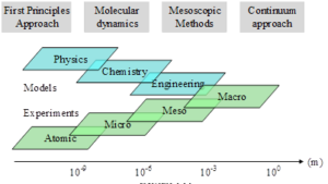
The nanoscale refers to the atomic and electronic levels, and its main method is first principles, which is based on quantum theory, calculates the electronic structure of atoms, and can be used to study bonding between atoms as well as alloying effects. Molecular dynamics, Monte Carlo and other methods are mainly used to study the dislocation evolution and local inelastic deformation processes at the grain scale.
The main research tools at the microscopic scale are dislocation dynamics and phase field. Dislocation dynamics is based on dislocation segments and uses elasticity theory, which can be used to determine the strengthening effect of dislocations. Phase field analysis is based on the mean field and diffusion law, and the method examines the tissue evolution and phase diagram prediction caused by phase transformations.
The main methods in the mesoscopic field include crystal plasticity finite elements and cellular automata. Among them, the crystal plasticity finite element mainly relies on the crystal plasticity theory to study the mechanical behavior of anisotropy of single crystals and polycrystals, the material orientation evolution process (weaving, etc.) and material failure or fracture behavior.
The macroscopic field mainly adopts the finite element method to solve partial differential equations using a continuous medium model.
TiAl intermetallic compound is a new type of lightweight high-temperature structural material with a series of unique mechanical and physical properties. Such as low density, high specific strength, excellent resistance to titanium fire, oxidation and high temperature creep properties, and at 900 \(\mathtt{{}^\circ\!{C}}\) can still maintain a high specific strength and specific stiffness. Thanks to the above excellent characteristics, TiAl intermetallic compounds have broad application prospects in many fields such as aerospace, automotive industry and gas turbine engines. In particular, it can largely improve the performance of aero-engine turbine blades, which has great potential in the future.
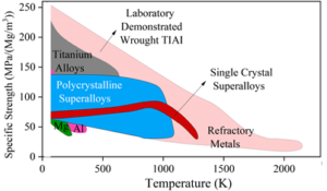
Figure 2 gives a comparison of the temperature dependence of the specific strength of TiAl intermetallic compounds with the performance. It can be seen that TiAl intermetallic compounds possess the highest specific strength in the temperature range below 900 \(\mathrm{{}^\circ}\)C. Since the interatomic bonding bonds of intermetallic compounds have some characteristics of both covalent and metallic bonds, they exhibit excellent properties such as higher high-temperature strength, high modulus of elasticity, good high-temperature creep resistance and high-temperature microstructure stability. At the same time, TiAl intermetallic compounds also have certain room temperature toughness, plasticity and crack extension resistance.
In the TiAl system, intermetallic compound phases such as \({\rm Ti}_{{\rm 3}} {\rm Al}\), TiAl, \({\rm TiAl}_{{\rm 2}}\) and \({\rm TiAl}_{{\rm 3}}\) exist. The crystal structure of \({\rm \gamma -TiAl}\) is a tetragonal \({\rm Ll}_{{\rm 0}}\)-ordered structure, in which Al atoms in the (001) face and Ti atoms in the (002) face are arranged in alternating rows along the crystal axis c. The (002) face is a tetragonal 5-ordered structure. The structure of \({\rm Ll}_{{\rm 0}}\) is ordered by the FCC crystal structure, and there is a difference in the length of the (001) direction from (100) and (010) due to the different radii of the Ti and Al atoms. c/a value increases from 1 to 1.02. And when the Al content increases, the value of c/a also increases. The crystal structure of \({\rm \gamma -TiAl}\) is shown in Figure 3. Its lattice parameters are, a=b=0.395 nm and c=0.407 nm. This ordered structure breaks some symmetry operations of the FCC monocrystalline cells in two main ways:

c/a axis ratio
Since the c/a axis ratio of \({\rm \gamma -TiAl}\) is not 1, this results in a loss of symmetry in some directions.
Symmetry manipulation of atomic types
Due to the ordering of the atomic arrangement, the \(\mathrm{<}\)hkl\(\mathrm{>}\) directions that are equivalent in face-centered cubic (FCC) metals are no longer equivalent in \({\rm \gamma -TiAl}\) of the \({\rm Ll}_{{\rm 0}}\) structure.
The microstructures of TiAl intermetallic compound materials have a variety of morphologies, and due to the different phase morphologies in biphasic alloys, four typical microstructures exist for \({\rm \gamma -TiAl}\)-based alloys, monocrystalline morphology, bicrystalline morphology. Tricrystalline morphology, and polycrystalline morphology. Among them, the bicrystalline structure is the most typical.
Twinning is also an important mechanism of plastic deformation, and twinning deformation occurs at specific crystal faces along specific crystal directions, so that dislocation slip can be used to describe twinning deformation [18]. Similar to dislocation slip, twinning deformation initiates when the decomposed shear stress on the twin system is greater than the critical shear stress. The contribution of twins to the plastic deformation of a crystal is measured by the ratio of the generated twin volume to the crystal volume, which is the twin volume fraction of the twin system [19], and is introduced into the crystal eigenstructure equation as follows.
The average shear strain generated by twinning is shown schematically in Figure 4, and the average shear strain generated by uniform shear in the twinned system \({\rm \gamma -TiAl}\) is indicated by \(\gamma ^{(B)}\): \[ \gamma ^{(\beta )} =\gamma _{T} f^{(\beta )} , \tag{1}\] where, \(\gamma _{T}\) is the twin shear strain, which takes the value of 0.705 for crystals with face-centered cubic structure.
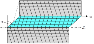
The left and right sides are derived for time to obtain the twin shear strain rate: \[ \dot{\gamma }^{(\beta )} =\gamma _{T} \dot{f}^{(\beta )} , \tag{2}\] where \(\dot{f}^{(\beta )}\) is the rate of change of the twin volume fraction, and its evolution equation is described according to Schmid’s law, following a law similar to dislocation slip: \[\ \left\{\begin{array}{ll} {\dot{f}^{(\beta )} =\dot{f}_{0}^{(\beta )} \left(\frac{\tau ^{(\beta )} }{g^{(\beta )} } \right)^{m} } {if:\tau ^{(\beta )} >g^{(\beta )} >0} \\ {\dot{f}^{(\beta )} =0} {if:\tau ^{(\beta )} <g^{(\beta )} } \end{array}\right. , \tag{3}\] where \(\dot{f}_{0}^{(\beta )}\) is the reference shear strain rate for twin deformation.
Combining dislocation slip and twin deformation, the total plastic deformation gradient is expressed as: \[\ L^{p} =\dot{F}^{p} F^{p-1} =\left(1-f_{v} \right)\sum _{\alpha =1}^{12}S^{(\alpha )} \dot{\gamma }^{(\alpha )} +\sum _{\beta =1}^{4}S^{(\beta )} \gamma _{T} \dot{f}^{(\beta )}, \tag{4}\] \[\ f_{v} =\sum _{\beta =1}^{n}f^{(\beta )}, \tag{5}\] , where \(f_{v}\) is the sum of the twin volume fractions and \(n\) is the number of twin systems.
The \({\rm \gamma -TiAl}\) intermetallic compounds with bicrystalline structure are densely arranged hexagonal \({\rm D}_{{\rm 0}} {\rm 19}\) structures with axial ratio c/a=0.8 and a=0.575 nm, c and a are lattice constants and their crystal structures are shown in Figure 5 [20]. The \({\rm \gamma -TiAl}\) intermetallic compounds of the bicrystalline structure are typically hard and brittle phases, which are difficult to deform plastically at room temperature, and fracture occurs when the plastic deformation is small. This is mainly due to the fact that the \(\alpha _{2}\)-phase has fewer movable slip systems, and the dislocation slip resistance along the C-axis direction is extremely difficult to slip, making it difficult to coordinate the deformation in all directions, and thus exhibiting poor plasticity.

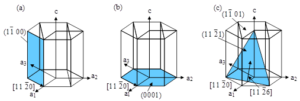
The dislocation slip of \({\rm \gamma -TiAl}\) intermetallic compounds with bicrystalline structure is shown in Figure 6, where 6(a) is the column surface slip system, 6(b) is the basal surface slip system, and 6(c) is the conical surface slip system [21]. It can be found that the dislocation slip of \({\rm \gamma -TiAl}\) intermetallic compounds with bicrystalline structure usually occurs on the column surface \(\left\{1\bar{1}00\right\}\left\langle 11\bar{2}0\right\rangle\), the basal surface (0001) \(\left\langle 11\bar{2}0\right\rangle\) and the conical surfaces \(\left\{\bar{1}\bar{1}21\right\}\left\langle 11\bar{2}6\right\rangle\) and \(\left\{11\bar{2}2\right\}\left\langle \bar{1}\bar{1}23\right\rangle\). Among them, the column surface slip is easily observed and its critical shear stress is minimized. The basal plane slip system can also be observed with a relatively large Schmidt factor, and its critical shear stress is about 2-3 times that of the column plane slip system. Conical slip systems are rarely observed, have the highest critical shear stress, and are very difficult to slip.
For the twinning deformation of \({\rm \gamma -TiAl}\) intermetallic compounds with bicrystalline structure, deformation twins were observed at temperatures higher than 1000 \(\mathrm{{}^\circ}\)C and when the compression axis was close to the C-axis, and the critical shear stress of the twinned system was about 50 MPa at 1000 \(\mathrm{{}^\circ}\)C, which decreases with the increase of temperature.
The construction of the finite element simulation model of the bicrystalline structure \({\rm \gamma -TiAl}\) of the intermetallic compound is divided into two steps: determining the base vectors after grain rotation and building the bicrystalline \({\rm \gamma -TiAl}\) model.
The basis vectors were determined using the following relation: \[\ \left[\begin{array}{ccc} {u} & {r} & {h} \\ {v} & {s} & {k} \\ {w} & {t} & {l} \end{array}\right]=\left[\begin{array}{ccc} {\Delta g_{11} } & {\Delta g_{12} } & {\Delta g_{13} } \\ {\Delta g_{21} } & {\Delta g_{22} } & {\Delta g_{23} } \\ {\Delta g_{31} } & {\Delta g_{32} } & {\Delta g_{33} } \end{array}\right]\left[\begin{array}{ccc} {u_{0} } & {r_{0} } & {h_{0} } \\ {v_{0} } & {s_{0} } & {k_{0} } \\ {w_{0} } & {t_{0} } & {l_{0} } \end{array}\right] , \tag{6}\] where \(\Delta g\left(\left[r_{1} I_{2} r_{3} \right],\delta \right)\) is the rotation matrix: \[ \begin{array}{l} {Jg\left(\left[r_{1} r_{2} r_{3} \right],\delta \right)} \\ {=\left[\begin{array}{ccc} {\left(1-r_{1}^{2} \right)\cos \delta +r_{1}^{2} } & {r_{1} r_{2} (1-\cos \delta )+r_{3} \sin \delta } & {r_{1} r_{3} (1-\cos \delta )-r_{2} \sin \delta } \\ {r_{1} r_{2} (1-\cos \delta )-r_{3} \sin \delta } & {\left(1-r_{2}^{2} \right)\cos \delta +r_{2}^{2} } & {r_{2} r_{3} (1-\cos \delta )+r_{1} \sin \delta } \\ {r_{1} r_{3} (1-\cos \delta )+r_{2} \sin \delta } & {r_{2} r_{3} (1-\cos \delta )-r_{1} \sin \delta } & {\left(1-r_{3}^{2} \right)\cos \delta +r_{3}^{2} } \end{array}\right]} \end{array} , \tag{7}\], where \(\left[r_{1} I_{2} r_{3} \right]\) is the rotation axis and \(\delta\) is the rotation angle.
Bicrystalline structure \({\rm \gamma -TiAl}\) intermetallic compounds with different grain boundaries of the different orientations of each grain as shown in Table 1, \(\left[{\rm u}_{{\rm 0}} {\rm v}_{{\rm 0}} {\rm w}_{{\rm 0}} \right]\) represents the basis vector of grain 1, \(\left[{\rm uvw}\right]\) is the basis vector obtained after grain 1 rotates around the rotation axis by a certain angle, and the two grains at the interface to form an overlap position dot matrix. The calculation process of determining the basis vectors of grain 1 after rotation is accomplished by writing a C language program, and the unknown quantities to be input are the rotation axis \(\left[{\rm uvw}\right]\), the rotation angle \(\theta\) and the basis vectors of the initial grain 1 to obtain the basis vectors of grain 2. In this case, the selection of the basis vectors of grain 1 is referred to Grain Boundary studio Java.
| Double crystal | Crystal grain 1 | Crystal grain 2 | \(\mathrm{\sum}\) | \(\theta \) | Axis of rotation | ||||
| 1 | [-110] | [11-2] | [111] | [-111] | [112] | [-1-11] | 3 | 108.5\(\mathrm{{}^\circ}\) | [-110] |
| 2 | [01-1] | [111] | [2-1-1] | [0-1-1] | [-111] | [211] | 5 | 72.5\(\mathrm{{}^\circ}\) | [01-1] |
| 3 | [110] | [012] | [02-1] | [10-1] | [20-1] | [021] | 5 | 36.8\(\mathrm{{}^\circ}\) | [100] |
| 4 | [100] | [-11-4] | [2-2-1] | [110] | [1-1-4] | [2-21] | 9 | 45.8\(\mathrm{{}^\circ}\) | [101] |
ABAQUS preprocessor is utilized to build a geometric model of the bicrystal structure \({\rm \gamma -TiAl}\). The size of the bicrystal is 0.5mm \(\mathrm{\times}\) 0.5mm \(\mathrm{\times}\) 1mm, and the grain boundary is located on the Z=0.5mm face. For the meshing of the bicrystal structure \({\rm \gamma -TiAl}\), C3D20R reduced-integral hexahedral cells are used, and the mesh edge length is taken as 0.05mm, totaling 5000 cells. For the top surface Z=2mm, set the boundary conditions \(U_{x} =U_{y} =0\), \(U_{z} =0.2\)mm, for the bottom surface Z=0, set the boundary conditions \(U_{x} =U_{y} =0\), \(U_{z} =-0.2\)mm, set the tensile time to 10s, the nominal strain of the bicrystal model is 0.05. The simulation is calculated by implicit algorithm, the maximum incremental step of the control time is 0.1s.
The material parameters (e.g., modulus of elasticity parameter, strain rate sensitivity factor, reference shear strain rate, hardening coefficient, etc.) for the bicrystalline structure \({\rm \gamma -TiAl}\) were accomplished by writing the material data card for the INP file in ABAQUS. The computational modeling was done using the power-exponential hardening formula proposed by Yes Asaro and Needleman: \[\ h_{\alpha \alpha } =h_{0} \sec h^{2} \left|\frac{h_{0} \gamma }{\tau _{s} -\tau _{0} } \right| . \tag{8}\]
In the formula, the critical shear stress \(\tau _{0}\) of each normal slip system in bicrystal structure \({\rm \gamma -TiAl}\) is 130 MPa, and the critical shear stress \(\tau _{0}\) of each superslip system is 200 MPa. The saturated flow stress \(\tau _{s}\) of the first stage of uniaxial stretching of bicrystal \({\rm \gamma -TiAl}\) is taken as 1.2 times of the initial critical shear stress, and the initial hardening modulus \(h_{0}\) of the normal slip system and superslip system are taken as 400 and 500 MPa, respectively. Strain rate sensitivity factor \(m\) is taken as 20 the reference shear strain rate \(\gamma _{0} {}^{(\alpha )}\) of each slip system is taken as 0.001 \({\rm s}^{{\rm -1}}\) and the hardening coefficient \(q\) is taken as 1.
Samples of bicrystalline structures \({\rm \gamma -TiAl}\) and \(\alpha _{2} {\rm -Ti}_{{\rm 3}} {\rm Al}\) (99.995%) for the high strain rate impact compression experiments were produced by Alfa Aesar, 6-phase shapes with dimensions of \(\Phi\)5 mm \(\mathrm{\times}\) 5 mm.Prior to twinning and deformation, high-purity bicrystalline structure \({\rm \gamma -TiAl}\) was annealed for 2 h in a vacuum furnace at 1053 K, \(10^{-4}\) Pa, and then cooled with the furnace.
The bicrystalline \({\rm \gamma -TiAl}\) and \(\alpha _{2} {\rm -Ti}_{{\rm 3}} {\rm Al}\) intermetallic materials used in the experiment were cast, of which the dimensions of the uranium specimen for the high strain rate impact spreading experiment were 10 \(\mathrm{\times}\) 5 \(\mathrm{\times}\) 5 mm, and the dimensions of the \({\rm \gamma -TiAl}\) specimen for the quasi-static opening and shrinking experiment were 10 \(\mathrm{\times}\) 6.5 \(\mathrm{\times}\) 4.5 mm. The \({\rm \gamma -TiAl}\) specimen for the quasi-static tensile experiment was of the “dogbone” configuration, with the middle part of the specimen measuring 10 mm in length and 20 mm in total length. Horizontal section length of 10 mm, the total length of the specimen 20 mm, thickness of 1 mm.
Preparation of specimens for EBSD analysis
The preparation of EBSD specimens for the bicrystalline structure of \({\rm \gamma -TiAl}\) intermetallic compounds is complicated. On the one hand, the atomic number of Ti is large, and the backscattered electron escape depth is shallow, which requires higher surface quality. On the other hand, the surface of Ti is easy to be oxidized, and the oxidized layer can easily degrade the quality of the backscattered diffraction pattern. Therefore, for the \({\rm \gamma -TiAl}\) specimens before and after deformation, in addition to the same grinding and polishing steps as that of metallic Ti, two electrolytic polishing methods need to be used in order to prepare a clear EBSD surface for Kikuchi pattern analysis.
The specific method is:
The electrolytic solution consisting of 40% ethanol, 30% ethylene glycol and 30% phosphoric acid was firstly used to electrolyze the surface for 5-10 min at 10-15 V. The surface was cleaned twice with white rice water, propanol and hot air.
Then electrolyze in 10% phosphoric acid and 90% deionized water solution to passivate the specimen surface to reduce the oxidation rate.
Finally, it was cleaned with water and propanol, blown dry and quickly put into the vacuum chamber.
TEM analysis technique
TEM analysis was performed on a FEI F20 transmission electron microscope and a Titan G2 60-300 spherical aberration corrected scanning transmission electron microscope to identify the type of twins in specific areas of the specimen after deformation, and the specimens for TEM analysis were prepared by a focused Ga ion beam (FIB). The specific procedure was as follows:
Step 1, In the first step, a protective layer was deposited on the surface of the sample of interest with an electron beam followed by ion beam deposition to ensure that the surface structure was not damaged by the ion beam.
Step 2, In the second step, large-beam etching was performed on each side of the deposited layer.
Step 3, In the third step, the bottom and side edges were cut off.
Step 4, In the fourth step, the sampling tip and the injected gas needle were placed close to the sample.
Step 5, connect the needle tip and sample with Pt deposition.
Step 6, lift the sample bonded to the tip of the needle.
In the seventh step, the sample at the tip of the probe was connected to the Grid of the TEM by Pt deposition, and then the connection between the tip of the needle and the sample was severed by an ion beam.
In the eighth step, the final thinning of the sample was carried out until the thickness that could be observed by the TEM, and the TEM analysis was performed.
Schmidt factor \(\mu\) analytical technique
The Schmidt factor \(\mu\) (SF) analytical technique is used to analyze the shear stresses (or shear stresses) acting on the slip and metamorphic surfaces during slip or twinning to evaluate the ease of initiation of the slip system or metamorphic system.An idealized assumption of SF analysis is that the direction of the stresses within the grains is in the same direction as the macroscopic stress direction in the specimen. Figure 7 shows a schematic of the SF analysis, with the external force oriented along \(F\), perpendicular to \(F\) with a cross-sectional area of \(A_{0}\), and slip or twinning occurring in the cross-section with area \(A\). The angle between slip or twinning direction \(n\) and \(F\) is \(\varphi\), and the angle between slip direction \(b\) and \(F\) is \(\lambda\). Therefore, the slice stress acting on the slip or twinning surface along the slip or student direction is:
\[ \tau {\rm =}\frac{F\cos \lambda }{\frac{A_{0} }{\cos \varphi } } =\frac{F}{A_{0} } \cos \varphi \cos \lambda =\sigma \cos \varphi \cos \lambda =\sigma \mu , \tag{9}\] where \(\mu =\cos \varphi \cos \lambda\) is the Schmid factor.
When \(\varphi =\lambda =45{}^\circ\), \(\mu\) is the maximum value of 0.5, corresponding to the body orientation is the specimen’s most “soft” orientation. Therefore, most of the actual slip and metamorphic surface traces appear at an angle of 45\(\mathrm{{}^\circ}\) to the external load. In the case of twins or slip systems, the larger the value of \(\mu\), the easier the activation of the twinned variant or slip system is.

The actual SF value is calculated in the coordinate system of the parent grain, and the index of the slip surface or twin surface in the parent grain can be obtained by EBSD test. The index of the external load direction in the coordinate system of the opposite grain can also be measured by EBSD. Based on the slip direction (or twinning direction) indices of the specific alternative slip system (or twinning system), the pinch angles \(\varphi\) and \(\lambda\) can be calculated, respectively, to obtain the SF values.
The properties in the ground state of the two phases \({\rm \gamma -TiAl}\) and \(\alpha _{2} {\rm -Ti}_{{\rm 3}} {\rm Al}\) in the bicrystalline TiAl intermetallic compounds are mainly investigated, including the phonon dispersion curves and the density of the projected states, the elastic constants and the mechanical properties in the ground state. On the basis of the bicrystalline TiAl model, the Schmidt factor \(\mu\) analytical technique (SF) is used to calculate the slip energy barriers and the twin deformation mechanism of \({\rm \gamma -TiAl}\) and \(\alpha _{2} {\rm -Ti}_{{\rm 3}} {\rm Al}\) in the critical shear stress study, and the dislocation slip dynamics of phases \({\rm \gamma -TiAl}\) and \(\alpha _{2} {\rm -Ti}_{{\rm 3}} {\rm Al}\) are investigated.
The space group and lattice parameters of the habitual cells at a temperature of 0 K for the experiments in this paper using \({\rm \gamma -TiAl}\) and \(\alpha _{2} {\rm -Ti}_{{\rm 3}} {\rm Al}\) are shown in Table 2. The lattice constants of the face-centered orthorhombic structure of \({\rm \gamma -TiAl}\) used are a=b=3.998 Å, c=4.056 Å, and c/a=1.015, respectively. The lattice constants of the densely arranged hexagonal structure of \(\alpha _{2} {\rm -Ti}_{{\rm 3}} {\rm Al}\) are a=b=5.784 Å, c=4.635 Å, c/a=0.801.
| Space group | a (Å) | c (Å) | c/a | |
| \(\rm \gamma -TiAl\) | P4/mmm | 3.998 | 4.056 | 1.015 |
| 3.997 | 4.056 | 1.015 | ||
| 3.976 | 4.032 | 1.015 | ||
| \(\alpha _2 \rm -Ti_\rm 3 \rm Al\) | \(\rm P6_\rm 3 \)/mmc | 5.784 | 4.635 | 0.801 |
| 5.707 | 4.616 | 0.809 | ||
| 5.712 | – | – | ||
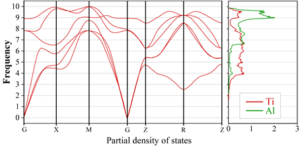
The phonon properties of \({\rm \gamma -TiAl}\) were calculated on a 3 \(\mathrm{\times}\) 3 \(\mathrm{\times}\) 3 supercell using the finite displacement method. Based on the forces calculated on the supercells with reduced atomic displacements, the atomic force constants were derived using the Phonopy package, and the calculated phonon dispersion curves (PBAND) and phonon density of states (PDOS) are shown in Figure 8. The motion in the phonon dispersion curves is almost exclusively associated with Ti atoms, which have lower energy frequencies than Al atoms, which is consistent with the fact that Al atoms are lighter than Ti atoms.
The phonon properties of \(\alpha _{2} {\rm -Ti}_{{\rm 3}} {\rm Al}\) were calculated on a 2 \(\mathrm{\times}\) 2 \(\mathrm{\times}\) 2 supercell as shown in Figure 9. The analysis of the density of phonon states projected onto Ti and Ti species clearly shows that the acoustic dispersion curve is almost entirely Ti atom dependent. This result is consistent with the mass ratio between Al and Ti atoms and the stoichiometry (1:3). As for the optical modes, they are related to the Al atoms. The small gaps in the phonon spectra compared to their \({\rm \gamma -TiAl}\) are \(\alpha _{2} {\rm -Ti}_{{\rm 3}} {\rm Al}\) unique to this structure.
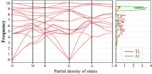
In order to confirm the stability of the constructed \({\rm \gamma -TiAl}\) and \(\alpha _{2} {\rm -Ti}_{{\rm 3}} {\rm Al}\) model structures, the phonon dispersion curves (PBAND) and the phonon density of states (PDOS), which represent the collective vibrational modes of the atoms that make up the material, were calculated, respectively. The results of the phonon dispersion curves (PBAND) and the phonon density of states (PDOS) along the high symmetry direction through the Brillouin zone show that neither of the plots shows unstable branches (an unstable branch is generally a branch with a negative vibrational frequency), indicating that both \({\rm \gamma -TiAl}\) and \(\alpha _{2} {\rm -Ti}_{{\rm 3}} {\rm Al}\) are dynamically stable.
When performing DFT calculations using VASP software, the choice of cell size affects the accuracy and efficiency of the results. The more atoms in the supercell model, the closer it is to the actual structure of the simulated material, but this correspondingly increases the amount of calculation. Therefore, it is particularly important to perform a convergence test of the supercell size before performing large-scale calculations. Through the convergence test, a suitable supercell size can be determined, so as to minimize the amount of computation and improve the computational efficiency while ensuring the computational accuracy.
Here, the effect of supercell size on the generalized layer misfit energy of the \({\rm \gamma -TiAl}\)\({\rm a}/6\left\langle 11\bar{2}\right. ]\left\{111\right\}\)-twin and \(\alpha _{2} {\rm -Ti}_{{\rm 3}} {\rm Al}\)\({\rm a}/3{\rm <}1010\left\{111\right\}\)-twin systems is tested separately. In constructing the supercell models, a vacuum layer of 15 Å is introduced normal upwards on all supercell model layer error surfaces in order to avoid interactions between periodically repeating atomic layers. The test results of the cell sizes are shown in Table 3, and it can be seen that, for the \({\rm \gamma -TiAl}\)\({\rm a}/6\left\langle 11\bar{2}\right. ]\left\{111\right\}\)-twin system, the error in the layer error energy between the supercells of 1 \(\mathrm{\times}\) 2 \(\mathrm{\times}\) 4-inch size and the supercells of 1 \(\mathrm{\times}\) 2 \(\mathrm{\times}\) 6-inch size is about 5% or so. And the layer error energy errors between the 1 \(\mathrm{\times}\) 2 \(\mathrm{\times}\) 8-inch supercell and the 1 \(\mathrm{\times}\) 2 \(\mathrm{\times}\) 10-size supercell are about 4.05% and 3.78%, respectively. And using the 1 \(\mathrm{\times}\) 2 \(\mathrm{\times}\) 6-size supercell, it has been able to accurately describe the generalized layer error energy properties of \({\rm \gamma -TiAl}\).
| Crystal Cell size | Atomic number | K value | Fault location | Generalized fault energy \(\rm mJ\)… \(m^{-2}\) | Error | |
| \(\rm \gamma -TiAl\) | 1\(\times \)2\(\times \)4 | 32 | 4\(\times \)3\(\times \)1 | a/6\(\rm <11\bar{2}\) | 131.50 | 5.34% |
| 1\(\times \)2\(\times \)6 | 48 | 4\(\times \)3\(\times \)1 | a/6\(\rm <11\bar{2}\) | 173.57 | 4.98% | |
| 1\(\times \)2\(\times \)8 | 64 | 4\(\times \)3\(\times \)1 | a/6\(\rm <11\bar{2}\) | 178.06 | 4.05% | |
| 1\(\times \)2\(\times \)10 | 80 | 4\(\times \)3\(\times \)1 | a/6\(\rm <11\bar{2}\) | 183.45 | 3.78% | |
| \(\alpha _2 \rm -Ti_\rm 3 \rm Al\) | 1\(\times \)2\(\times \)4 | 32 | 2\(\times \)6\(\times \)1 | a/3\(\rm <10\bar{1}0\rm >\) | 194.58 | 8.25% |
| 1\(\times \)2\(\times \)6 | 48 | 2\(\times \)6\(\times \)1 | a/3\(\rm <10\bar{1}0\rm >\) | 289.33 | 6.52% | |
| 1\(\times \)2\(\times \)8 | 64 | 2\(\times \)6\(\times \)1 | a/3\(\rm <10\bar{1}0\rm >\) | 312.62 | 5.84% | |
| 1\(\times \)2\(\times \)10 | 80 | 2\(\times \)6\(\times \)1 | a/3\(\rm <10\bar{1}0\rm >\) | 306.50 | 5.05% | |
The \({\rm \gamma -TiAl}\) twin system and \(\alpha _{2} {\rm -Ti}_{{\rm 3}} {\rm Al}\) of the bicrystalline structure are deformed through complex deformation mechanisms, including \({\rm \gamma }\) phases that can be deformed by sliding of ordinary dislocations, sliding of superdislocations, and twinning. Ordinary dislocations can reduce their energy by dissociating on the \(\left\{111\right\}\) sliding surface by planar or nonplanar dissociation: \[{\rm a/2<1}\bar{{\rm 1}}{\rm 0}\to {\rm a/6<}\bar{{\rm 2}}{\rm 11]+CSF+a/6<}\bar{{\rm 1}}{\rm 2}\bar{{\rm 1}}\]
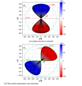
The assumed planar structure and the actual asymmetric core structure of the \({\rm \gamma -TiAl}\)-twin system of the bicrystalline structure are shown in Figure 10. It demonstrates the nonzero dislocation component of the \({\rm a/2<110}{\rm ]}\left\{{\rm 111}\right\}\)-screw dislocation in the TiAl twin system. For planar dissociation, the dislocation core diffuses into the \(\mathrm{\{}\)111] plane. For non-planar dissociation, the dislocation core spreads to two equivalent \(\mathrm{\{}\)111] planes. It can be seen that the \({\rm \gamma -TiAl}\)-structure becomes asymmetric and non-planar under the twin deformation, the screw dislocations become planar under the applied stresses, and the planar dislocations are free to move forward.
As a typical hexagonal metal, titanium has relatively few slip systems and is less capable of adapting to machining deformations than aluminum. The critical shear stresses required for the activation of different deformation mechanisms in pure titanium are different, and Table 4 lists the critical shear stresses obtained from experimental simulations of TiAl intermetallic compounds with bicrystalline structures for different deformation mechanisms. It can be found that in TiAl titanium layers, the critical fractional stress required for columnar \(\mathrm{<}\)a\(\mathrm{>}\)slip and twin initiation is the smallest, and the critical fractional stresses required for the two bicrystalline structures of TiAl intermetallic compounds are 92 and 108 MPa, respectively. Critical shear stresses required for taper \(\mathrm{<}\)a\(\mathrm{>}\) and basal \(\mathrm{<}\)a\(\mathrm{>}\) slip with twin initiation are the next highest. Taper \(<c+a>\) slip with twin initiation requires the highest critical fractional shear stress, and the two bicrystal structures are numerically equivalent.
|
Slip/twin
system |
Basal
\(\mathrm{<}\)a\(\mathrm{>}\) |
Prismatic
\(\mathrm{<}\)a\(\mathrm{>}\) |
Pyramidal
\(\mathrm{<}\)a\(\mathrm{>}\) |
Pyramidal
\(\mathrm{<}\)c+a\(\mathrm{>}\) |
Extension
twinning |
Contraction
twinning |
| Plane | \(\mathrm{\{}\)0001\(\mathrm{\}}\) | \(\mathrm{\{}1\bar{1}00\mathrm{\}}\) | \(\mathrm{\{}1\bar{1}01\mathrm{\}}\) | \(\mathrm{\{}1\bar{1}01\mathrm{\}}\) | \(\mathrm{\{}1\bar{1}02\mathrm{\}}\) | \(\mathrm{\{}11\bar{2}2\mathrm{\}}\) |
| Direction | \(<11\bar{2}0>\) | \(<11\bar{2}0>\) | \(<11\bar{2}0>\) | \(<1\bar{2}13>\) | \(<10\bar{1}0>\) | \(<\bar{1}\bar{1}\bar{2}3>\) |
| \(\rm \gamma -TiAl\) | 181 MPa | 92 MPa | 140 MPa | 260 MPa | 170 MPa | 225 MPa |
| \(\alpha _2 \rm -Ti_\rm 3 \rm Al\) | 190 MPa | 108 MPa | 165 MPa | 260 MPa | 228 MPa | 235 MPa |
The number of independent slip systems with different slip mechanisms of the titanium layer is shown in Table 5, and when deformed at room temperature, the vertebral slip that is easy to start in the titanium layer \(\mathrm{<}\)a\(\mathrm{>}\)can only provide three independent slip systems (\(\mathrm{<}\)a\(\mathrm{>}\)the three independent slip systems of the cone are equivalent to \(\mathrm{<}\)a\(\mathrm{>}\)\(\mathrm{<}\)a\(\mathrm{>}\)the cross-slip results of three base planes and two cylindrical surfaces). Therefore, in order to meet the Von Mises criterion to achieve the free deformation of polycrystals, it is necessary to \(\mathrm{<}\) c+a\(\mathrm{>}\)slip or twin involved deformation.
| Slip system | Slip plane | Slip direction | Independent slip systems |
| Basal \(\mathrm{<}a\mathrm{>}\) | \(\mathrm{\{}0001\mathrm{\}}\) | \(<11\bar{2}0>\) | 3 |
| Prismatic \(\mathrm{<}\)a\(\mathrm{>}\) | \(\mathrm{\{}1\bar{1}00\mathrm{\}}\) | \(<11\bar{2}0>\) | 2 |
| Pyramidal \(\mathrm{<}\)a\(\mathrm{>}\) | \(\mathrm{\{}1\bar{1}01\mathrm{\}}\) | \(<11\bar{2}0>\) | 3 |
| Pyramidal \(\mathrm{<}\)c+a\(\mathrm{>}\) | \(\mathrm{\{}1\bar{1}00\mathrm{\}}\) | \(<\bar{1}\bar{1}\bar{2}3>\) | 4 |
Twinning is an important part of the plastic deformation mechanism of titanium, and the common twinning modes in titanium layers are shown in Table 6. At room temperature, the most common twinning modes in pure titanium are \(\mathrm{\{}\)\(10\bar{1}2\)\(\mathrm{\}}\) tensile twins and \(\mathrm{\{}\)\(10\bar{1}\bar{1}\)\(\mathrm{\}}\) compression twins due to the small critical shear stresses and shear amounts. Since the twinning deformation is unidirectional shear, the type of deformation twin depends mainly on the geometrical relationship between grain orientation and applied stress. When tensile stresses parallel to the c-axis of the crystallography of titanium grains are present or when there is a large angle between the compressive stresses and the c-axis, there is a tendency to activate \(\mathrm{\{}\)\(10\bar{1}2\)\(\mathrm{\}}\) tensile twins. When there is a compressive stress parallel to the c-axis or a tensile stress perpendicular to the c-axis, it tends to activate \(\mathrm{\{}\)\(10\bar{1}\bar{1}\)\(\mathrm{\}}\) compression twins.
|
Twinning
mode |
Twinning
plane |
Twinning
direction |
Misorientation
axis |
Misorientation
angle |
Shear
strain |
|
Extension
twinning |
\(\mathrm{\{}10\bar{1}2\mathrm{\}}\) | \(<10\bar{1}\bar{1}>\) | \(<1\bar{2}20>\) | 85.2\(\mathrm{{}^\circ}\) | 0.183 |
| \(\mathrm{\{}11\bar{2}3\mathrm{\}}\) | \(<11\bar{2}6>\) | \(<\bar{1}0\bar{2}0>\) | 36.5\(\mathrm{{}^\circ}\) | 0.642 | |
| \(\mathrm{\{}11\bar{2}1\mathrm{\}}\) | \(<33\bar{2}6>\) | \(<\bar{1}100>\) | 87.3\(\mathrm{{}^\circ}\) | 0.545 | |
|
Contraction
twinning |
\(\mathrm{\{}10\bar{1}\bar{1}\mathrm{\}}\) | \(<10\bar{1}\bar{2}>\) | \(<\bar{1}2\bar{1}0>\) | 60.8\(\mathrm{{}^\circ}\) | 0.107 |
| \(\mathrm{\{}11\bar{2}\bar{2}\mathrm{\}}\) | \(<11\bar{2}\bar{3}>\) | \(<\bar{1}123>\) | 65.2\(\mathrm{{}^\circ}\) | 0.227 | |
| \(\mathrm{\{}1\bar{1}24\mathrm{\}}\) | \(<11\bar{2}1>\) | \(<\bar{1}100>\) | 75.6\(\mathrm{{}^\circ}\) | 0.234 |
The twinning behavior has an important effect on the mechanical properties of titanium layers, and its main mechanisms can be summarized as follows:
Changing the crystal orientation and changing the tendency of crystal slip.
Hall-Patch effect due to grain refinement by twin formation.
Formation of immovable dislocations through twinning boundary and dislocation interaction.
Since the twinning behavior is a shear along a specific direction, it drastically changes the spatial orientation of the crystal and has a large impact on the weave configuration of the material. Figure 11 shows the evolution of the weave structure of a bicrystalline structure \({\rm \gamma -TiAl}\) intermetallic compound layered configuration material with titanium layer during uniaxial stretching. Where 11(a)\(\mathrm{\sim}\)(d) are the statistical distributions of the grain boundary orientation difference angle of titanium layer in the \({\rm TiAl}\)-metallic compound layered configuration material under 0%, 1%, 2%, and 10% macroplastic deformation, respectively. With the increase of macroplastic deformation from 0% to 10%, the weave structure (LAGB) of the titanium layer is gradually enhanced from 40.5% to 63.79%, accompanied by the rotation of some of the titanium grains on the axis of the ND direction. Since the titanium layer has a strong basal plane weave, i.e., it exhibits titanium grains rotating in the crystallographic c-axis, indicating the initiation of columnar plane slip.
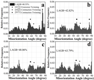
In the absence of laminar structural constraints, the initiation of \(\; \{ 11\bar{2}2\}\) compression twins is easily activated due to the large angle of the applied stresses to the crystallographic c-axis of most of the titanium grains, leading to a decrease in the weave strength of titanium. In contrast, in titanium-aluminum layered conformational materials, the initiation of \(\; \{ 11\bar{2}2\}\) compression twins is very limited, and the initial twins degenerate back to the basal weave orientation mainly through the de-twinning of \(\; \{ 10\bar{1}2\}\) tensile twins in order to coordinate the deformation, leading to an increase in the weave strength of the titanium layer.
In this paper, we analyze the twinning deformation mechanism of phases \({\rm \gamma -TiAl}\) and \(\alpha _{2} {\rm -Ti}_{{\rm 3}} {\rm Al}\) and the dislocation decomposition of the \({\rm \gamma -TiAl}\)\(\mathrm{\{}\)111) and \(\alpha _{2} {\rm -Ti}_{{\rm 3}} {\rm Al}\)\(\mathrm{\{}\)0001\(\mathrm{\}}\) basal planes in the bicrystalline structural \({\rm TiAl}\) alloys with \({\rm \gamma -TiAl}\) and \(\alpha _{2} {\rm -Ti}_{{\rm 3}} {\rm Al}\) as the study objects. It is found that the slip along \({\rm 1/2<1}\bar{{\rm 1}}{\rm 0]\{ 111)}\) in \({\rm \gamma -TiAl}\) has the highest form-nucleation barrier with high symmetry, and the deformation energy should be zero at the shear strain point 1.0 because of its high symmetry, which is not easily observed in room-temperature experiments. \({\rm \gamma -TiAl}\) The structure becomes asymmetric and nonplanar under the action of twin deformation, the screw dislocations become planar structures under the action of applied stresses, and the planar dislocations are free to move forward. For \(\alpha _{2} {\rm -Ti}_{{\rm 3}} {\rm Al}\) the same slip curve is produced only when the base surfaces slip alternately, and both \(\gamma\) surfaces exhibit triple symmetry.