
Three-dimensional (3D) braided composite is a whole network structure formed by interweaving carbon fiber yarns, which is a kind of designable and highly integrated composite material [1]. It is extensive used in aerospace, sports, shipbuilding, civil engineering and other industries [2].
According to the relevant literature, it is found that the suitable structure modeling of 3D braided composites is a necessary prerequisite to study its mechanical properties. By analyzing the braiding technique of this materials, it is found that it is a three-dimensional braiding structural material formed by yarns with fixed braiding rules. Due to its special braiding process, the material has a periodic braiding rule [3,4]. At present, most studies had adopted the idea of multi-scale analysis based on this periodic braiding rule, and established the spatial configuration of 3D braided composites gradually at micro, micro and macro scales, while few studies had established the full-size simulation model at the macro scale [5-7]. Therefore, this paper took 3D five-directional braided composite material as the research object, and established a full-size geometric structure model by analyzing its braiding process characteristics, so as to realize the computer simulation of the spatial configuration of 3D braided composites under different braiding technology parameters.
At present, the research on the construction of geometric models of 3D braided composites has achieved good results. Its spatial configuration is usually simplified by setting some reasonable assumptions. The constructed model has experienced theoretical model, unit cell model and full-size simulation model successively. With the rapid development of science technology and the introduction of CT scanning technique, the constructed model can more truly reflect the spatial structure of braided materials.
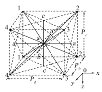
The research on the construction of spatial configuration of 3D braided composites first began in the 1980s, and most of the research models were established by theoretical formula derivation. For example, Chou and Kiang [8] developed three material models, namely the Mosaic model, the fiber undulation model, and the bridging model; Emehel and Shivakumar [9] proposed the fiber tow inclination model and the fiber tow collapse model; and Yang et al. [10] presented the fiber inclination model, as shown in Figure 1.
With the wide application on computer technology, researchers had adopted computer software to build geometric models of 3D braided composites gradually. This not only improved the efficiency of model construction, but also could establish a more accurate model reflecting the braiding structure, which laid a foundation for the subsequent numerical simulation analysis of materials.
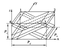
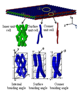
Most of the researchers divided the spatial structure of 3D braided composites into periodic elements by considering the periodic braiding law, and established the unit cell model for simulating the mechanical properties of 3D braided composites approximately. In addition, the assumptions for the material model were different, and the unit cell model was also different. For example, Freire et al. [11] used the 3DMAX software to construct three unit cell models, including the inner cell, surface cell, and corner cell model, as shown in Figure 2(a); Li et al. [12] adopted the ANSYS software for parametric programming to build the inner cell model of 3D five-directional braided composites [13], as shown in Figure 2(b); authors in [14,15] used Python language to write plugins to establish the unit cell model from the microscopic, mesoscopic, and macroscopic scales, as shown in Figure 2(c); Zhang and Xu [16] used Texgen, the open source software designed by Martin Sherburn at the University of Nottingham in UK, to parameterize three solid unit cell model, as shown in Figure 2(d). However, this model construction method was still simplified relatively. Although the influence of the surface cell and corner cell on the material had been considered, there was still a big difference between the constructed model and the actual braided structure. The three unit cell model was too complicated, which was not conducive to more complex numerical simulation research.


At present, part of the research results had carried out the computer structure simulation of 3D braided composites by considering the braiding rules, so as to establish the full-size braided structure model. This kind of model could reflect the characteristics of the braided structure of materials more directly. But because of the high requirements on the computer performance, the calculation workload was large, and the programming modeling was also difficult relatively.
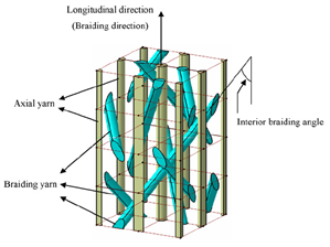
For example, Zuo et al. [17] used the Windows 200 NT Server platform and selected MATLAB + 3DMAX + AutoCAD VBA as the development tools to build a simulation program for 3D braided composite materials. The square and circular four-step braided composites model were generated as shown in Figure 3(a). Li et al. [18] used the CATIA-V5-R20 software to establish a 3D full-size mesoscopic geometric model, as shown in Figure 3(b).

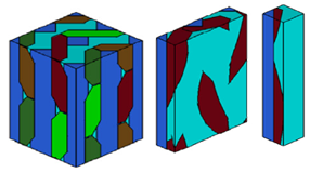
At present, there were few researches on the use of CT scanning technique to simulate the real material models [19-21]. For example, Fang et al. [20] reconstructed the orthotopic model of 3D braided composites based on Micro-CT image processing technology. At the same time, a more realistic spatial configuration was generated by considering the pore defects inside the material and solving the intrusion problem between yarns, as shown in Figure 4.

Different models were built in different references based on different material model assumptions, yarn cross section shapes and yarn bending and torsion settings, but all models could be applied to numerical simulation of mechanical properties of 3D braided composites approximately. However, there was still a significant gap between the three unit cell modeling method and the actual braided structure characteristics. Although the full-size model could reflect the actual braided structure more directly, it was very complicated for its establishment due to the complexity of the interwoven network structure of yarns in the materials. In addition, there were few researches on the establishment of full-size simulation models for 3D braided composites, which were not enough to meet the research requirements of the numerical simulation and the optimum structural design for 3D braided composites. Although the model built by CT scanning technology could reflect the actual braided structure more truly, it was difficult to carry out subsequent numerical simulation of materials due to the poor regularity of the solid model. Therefore, this paper studied the variation laws of yarn trajectories inside 3D five-directional braided composites, and relied on MATLAB+CREO computer platform to develop software programming, and realized the construction of geometric structure model.
Based on the 3D four-step braiding process, the 3D five-directional braided composites can be obtained by adding axial stationary yarn braiding in the longitudinal direction (the Z direction). Figure 5 shows the schematic diagram of 3D four-step five-directional braiding process. In this diagram, the braided yarns are marked by a number and the axial yarns are marked by a black circle.
The specific braiding process is as follows:
In step 1, the braided yarn carriers and the axial yarn carriers in the adjacent rows move one position alternately in the X direction;
In step 2, the braided yarn carriers in the adjacent columns move one position alternately in the Y direction;
In steps 3 and 4, the direction of the yarn carrier motion is object to that of step 1 and 2 respectively.
After the above four steps movement, the yarn arrangement on the machine chassis will be restored to the initial position, that is, a machine cycle is completed. Therefore, the length of the braided preform obtained by a machine cycle is defined as the braiding distance h, and the 3D four-step braided form is denoted as [m\(\times\)n], where m and n are the number of rows and columns of the braided yarns, respectively. Repeat the above four-step process and supplement by the “tightening” process, so that the adjacent braided yarns can contact each other and squeeze tight, and form a stable braiding preform finally. The total number of yarns N\({}_{t}\) in the 3D five-directional braided preform is as follows: \[\label{GrindEQ__1_} {l} {N_{b} =mn+m+n}, \\ {N_{z} =mn}, \\ {N_{t} =N_{b} +N_{z} }, \tag{1}\] where, N\({}_{b}\) and N\({}_{z}\) are the total number of braided yarns and axial yarns respectively.

In this braiding process, each yarn is driven by a separate carrier. The braided yarn carriers move in 3D four-step braiding mode, and the axial yarn carriers move with one step back and forth in the X direction.
Figure 6 showed the horizontal projection diagram of the motion tracks of a braided yarn and an axial yarn driven by the carrier to return to the initial position through six machines loop in the four-step 4\(\mathrm{\times}\)4 braiding process. It could be seen that their motion trajectories are different. The motion trajectories of braided yarns were distributed from the inside to the surface and even the edges, while the motion trajectories of axial yarns were only swing back and forth between the two positions in the row direction. Therefore, the motion behavior of braided yarns and axial yarns were described by different computer languages based on this difference in this paper.
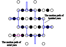
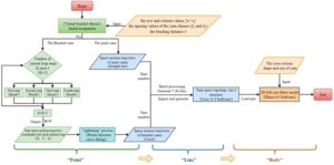
Figure 7 showed the schematic diagram of the computer simulation system flow of the 3D five-directional braided composite preform. In this paper, the braiding rules of each yarn were described by MATLAB R2016a computer language programming, that is, the parametric modeling of “point-line” yarn space curve structure was completed. By using CREO 11.0 computer as the solid model simulation platform, the “line-body” full-size solid structure model was completed by introducing the cross section shape and size of yarn. In this paper, based on the modeling idea of “point-line-body”, a computer simulation was carried out to simulate the spatial configuration of 3D five-directional braided composites. Then, an agreement between the full-size simulation model and the real fabric structure was verified.
Software MATLAB R2016a was used as a computer programming development platform. The program was mainly used to describe the motion trajectories of braided yarns and axial yarns, so as to obtain the spatial position data of 3D fabrics and the topological laws of spatial yarns. By setting the row and column values ([m\(\times\)n]) of the braided yarns, the number of braided cycles N and the spacing values of the yarn chassis (d\({}_{1}\) and d\({}_{2}\)), the “curve point” data of the braided yarns in the 3D five-directional braided composites under different braiding parameters could be obtained.
The specific operation procedure wss as follows:
The running program of braided yarn mainly included the mainprogram (mainprogram_ibl.m) and the calling subroutine (column_to_row_change_ibl.m; curve_fitting.m; bezier3.m; RecBraid1.m; RecBraid2.m; RecBraid3.m; RecBraid4.m) and the data processing program (mainibl.m). The running program of the axial yarn mainly included the main program (Z.m) and the data processing program (a.bat; mainiblz.m).
The initial position arrangement and assignment of 3D braided yarn. Set the initial position coordinates of each yarn in the plane grid pattern. Use a for loop statement, and the array Number(i,j) to store the position coordinate values of each yarn at each braided step. Taking four-step 4\(\mathrm{\times}\)4 braiding as an example, Figure 8 showed the setting of the initial position coordinates of the braided yarns.

The algorithm description of four-step braiding process. Use subroutine call in the function for describing four groups of programs: RecBraid1.m, RecBraid2.m, RecBraid3.m, and RecBraid4.m. And these four groups of programs were correspond to the four-step braiding rules. Set four steps as a computer loop.
Bézier function curve fitting. Connect the space coordinates of each yarn under each braided step which was obtained by the second step to form multiple fold lines. But the actual machine braiding would undergo a “tightening” process after completing a cycle, so that the braided yarn appeared as a curve of bending and twisting shape. Therefore, the Bezier 3.m program was written to achieve Bézier function curve fitting, which was used to describe the spatial motion trajectories of yarns after the “tightening” process.
The algorithm description of axial yarns. According to the characteristics of the motion tracks of the axial yarns, they were only swing back and forth with one step in the X direction. After the “tightening” process, the shape of the yarns could be regarded as a straight line in the Z direction approximately. Therefore, write the mainprogram (Z.m) and the data processing program (a.bat; mainiblz.m) for outputting the motion tracks of the axis yarns.
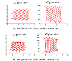
Taking 3D four-step (4\(\mathrm{\times}\)4) braided process as an example, set the number of rows and columns [m\(\times\)n] to be 4\(\mathrm{\times}\)4, the number of machine cyclic N to be 16, and the geometric dimensions of the structural parts to be Wx=6mm, Wy=6mm. When the braiding angle \(\alpha\) was 30\(\mathrm{{}^\circ}\), the spacing values of the yarn chassis d\({}_{1}\) was 1.4123mm, and the braiding distance h was 4.8923mm by the theoretical calculation. While when the braiding angle \(\alpha\) was 20\(\mathrm{{}^\circ}\), the spacing values of the yarn chassis d\({}_{1}\) was 1.4132mm, and the braiding distance h was 7.7604mm. The running result of the program was shown in Figure 9.
The MATLAB software was used to realize the batch output of yarns bending “line” data. The Creo 11.0 software was used to implement the batch modeling of yarns “body”. The shape and size of the yarns cross section were parameterized. Finally, mass used the “scanning” function to complete the construction of 3D braided geometric entity structure model, which improved the efficiency of full-size model simulation.
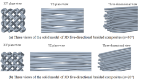
In order to verify the feasibility of the above computer simulation, take 3D four-step (4\(\mathrm{\times}\)4) braided process as an example. Set the number of rows and columns [m\(\times\)n] to be 4\(\mathrm{\times}\)4, the number of machine cyclic N to be 2, and the geometric dimensions of the structural parts to be Wx=6mm, Wy=6mm. Figure 10 was the 3D views of full-size model of 3D five-directional braided composites with the braiding angle of \(\alpha\)=30\(\mathrm{{}^\circ}\) and \(\alpha\)=20\(\mathrm{{}^\circ}\).
In order to facilitate the subsequent finite element analysis, it was necessary to avoid the phenomenon of intersecting yarns while simplifying the model. Set the cross section shape of the yarn to be circular, the cross section diameter of the braided yarns D\({}_{B}\)=0.5mm, the one of the inner axial yarn D\({}_{Z}\)=0.5mm, the one of the axial yarn on the surface boundary D\({}_{S}\)=0.35mm, and the one of the axial yarn on the conner boundary D\({}_{C}\)=0.33mm.
Compared with the full-size structural model at the braiding angle of 30\(\mathrm{{}^\circ}\) and 20\(\mathrm{{}^\circ}\), it could be found that with the decrease of the braiding angle, the braiding distance increases gradually, and the yarn weave structure becomes looser, which was consistent with the actual three-dimensional fabric weave.
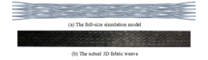
As shown in Figure 11, the established full-size model could better reflect the spatial configuration of 3D five-directional braided yarns, which was close to the actual fabric weave, and could obtain the shape and arrangement of yarns at any space placement. The results showed that the computer simulation model established in this paper is effective. By changing the input design values, the full-size structure model of 3D five-directional braided composites could be parameterized under different braided parameters.
According to the 3D four-step braiding process, the braiding process characteristics of 3D five-directional braiding composites were analyzed, and the layout and spatial structure characteristics of yarns in the 3D braiding composite were mastered. Meanwhile, on the basis of the developed model building program and the MATLAB+Creo computer modeling platform, the full-size geometric simulation model was parametrized built by considering the “point-line-body” modeling idea. The model could better reflect the interweaving of yarns in 3D braided composites, and was more similar to the actual fabric weave.
The authors would like to acknowledge the support provided by the University Natural Science Foundation of Jiangsu Province(Grant no.22KJB130008), the Basic Science Research and Social Livelihood Technology Program of Nantong (Innovation Program for Young Scientific and Technological Talents)( Grant no.JC12022079), the Provincial Science and Technology Cultivation Program of Jiangsu College of Engineering and Technology(Grant no. GYKY/2021/3), and the Jiangsu Vocational College Student Innovation and Entrepreneurship Cultivation Program (Innovation Practice Project).