
Modern power transmission relies heavily on high-voltage direct current (HVDC) transmission systems, which are utilized extensively throughout the world due to their great efficiency, stability, and capacity for long-distance transmission [1]. The precision and dependability of the DC current transformer, a crucial component of the HVDC system, in the transient steady-state operation of the system are directly tied to the safe and stable operation of the HVDC system. The DC current transformer measures, protects, and controls current. Consequently, there is a practical requirement and significant engineering significance for accurate field testing of DC current transformers [2,3].
The demands on DC current transformer performance are rising in tandem with the ongoing advancements in HVDC technology. DC current transformer design and testing face additional obstacles as a result of the increased demands placed on modern HVDC systems regarding transient characteristics, frequency responsiveness, and current measurement accuracy [4,5]. To guarantee the quality and dependability of measurement findings, DC current transformer field test equipment must not only operate in challenging engineering conditions but also tolerate a wide range of electromagnetic interference and noise [6]. Three basic categories of DC current transformer measurement principles exist: photoelectric, zero flux, and all-fiber optic. Key indications including step response, frequency response, and DC measurement accuracy need to be validated to guarantee the precision of their measurements. But there are still a lot of issues with the existing field test system in real-world use, like delay and harmonic interference, which have a negative impact on test findings accuracy [7,8].
Data processing, fiber optic transmission, digital-to-analog conversion, and other processes all take time when moving from analog signals from primary sensors to digital signals output via Ethernet or FT3. Particularly in high-precision measurements and synchronization tests, these delays can build up and cause inaccuracies in the measurement results [9,10]. DC current signals in real-world engineering settings typically have a high harmonic content, particularly when there are DC system defects, when the harmonic content rises dramatically. The accuracy of the test results may suffer as a result of these harmonics interfering with the measurement of the DC components. The precision of the A/D conversion, mistakes made during data processing, and system noise interference are the main sources of errors in the test system. To varying degrees, these inaccuracies will impact the test results’ accuracy [11].
A great deal of research has been done on the field testing of DC current transformers by domestic and international scholars. Study [12] created a fiber-optic synchronization magnetically modulated DC current comparator, which enhances anti-interference capability but is still unable to address the delay issue. Study [13] methodically contrasted several field test techniques and highlighted the benefits and drawbacks of each, but the latency and harmonic issues persist in real-world applications. GPS is used by [14] to accomplish synchronization testing; however, the absolute delay time cannot be precisely tested. used the wavelet transform to analyze the A/D sample data, which increased the measurement accuracy; however, there are issues with the wavelet base selection that require more research. Overall, the accuracy and dependability of the test results still need to be increased, and the current research techniques are still inadequate for addressing delay time and harmonic interference. This study presents a field closed-loop test technique based on high-precision synchronization module enhancement and empirical modal decomposition (EMD) filtering, with the goal of addressing the issues with the current DC current transformer field test system. The following are this paper’s principal benefits:
The error issue brought on by the delay is resolved by the addition of a high-precision synchronization module, which enables the simultaneous acquisition of the measured digital quantity and the standard source analog quantity. Because of this, the test system can function accurately even in the presence of varying transmission and data processing delays caused by various transformers.
The signal is acquired using an 18-bit high-precision A/D, and the sampled data is processed using the EMD algorithm.The measurement data is more accurate thanks to the EMD algorithm’s ability to extract the DC components and efficiently filter out the harmonic components. The EMD technique is easy to use and effective when compared to the wavelet transform, making it a good fit for engineering applications. In order to imitate the step current created during the transient process of the system, a step source system is designed for transient step response testing of DC current transformers. The system’s accuracy and viability are empirically confirmed to satisfy the requirements of the temporary test. Real-world engineering case testing is used to confirm the enhanced test system’s efficacy. According to the experimental findings, the enhanced test system performs exceptionally well in both steady state and transient tests, and the test results are more in line with standard values, preventing the appearance of data with significant mistakes.
The process of obtaining an analog signal from the primary sensor and outputting a digital signal via Ethernet or FT3 involves multiple delays in the DC current transformer. Firstly, there is a delay in the primary sensor’s transmission. Secondly, the analog voltage obtained from the primary sensor is sent to the remote module, requiring digital-to-analog conversion. Thirdly, the remote module transmits the digital current signal to the merging unit via fiber optics, requiring data processing frame compression. Finally, there is a delay in the data transmission. The merging unit receives the data and simultaneously schedules the data processing multiplexing program. Figure 1 illustrates this process. Data is received by the merging unit, which also schedules the data processing multiplexing synchronization program. The data is then sent and output by FT3 or Ethernet. Figure 1 displays the composition of absolute delay time. One of the most important factors for all devices is the absolute delay time, but protective control systems in particular need great real-time performance. As a result, this study offers a precise definition of delay time from the perspective of transformer use.
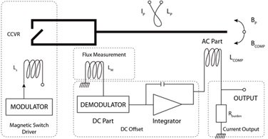
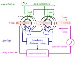
Figure 2 depicts the layout of the DC current transformer closed-loop test set. The tester receives an analog voltage signal as the standard output of the primary current as its input, while the digital current signal transmitted by the DC current transformer being tested is fed into the tester via the FT3/optical ETH. The signal conditioning input A/D module transforms the typical analog signal into a digital signal. The FPGA analyzes the digital signal under test as well as the reference digital signal. The processed digital signals are then passed into the PowerPC for further data processing and analysis in order to determine the DC and harmonic accuracy of the transformer under test.
The tester synchronizes the measured digital signal and the acquisition of the standard source analog signal using a high-precision synchronization module. Real-time synchronous closed-loop testing of DC current transformers is made possible, as illustrated in Figure 2, by precisely timing the analog-to-digital conversion of the standard analog signals and the measurement of the digital signals by the synchronization module during the FPGA message parsing and data analysis. The tester can function accurately even if the transmission delay and data processing delay varies because of different transformers because the data are precisely time-stamped throughout data reception and processing.
A condensed representation of the field test system is displayed in Figure 3. The measured current \(I_{{\rm c}}\)from the current transformer under test is the input to the tester via the FT3/optical ETH. The output of the tester is the actual error \(\varepsilon _{{\rm r}}\). The primary current is \(I_{{\rm s}}\), and the voltage input of the tester is the secondary current \(I_{{\rm b}}\)obtained by the current standardizer, the voltage obtained by the high-accuracy current transformer, and the standard resistor. The real mistake can be expressed as [16]. \[\begin{aligned} \label{GrindEQ__1_} \varepsilon _{{\rm r}}=& {\rm }\begin{array}{l} {} \end{array}\frac{\left|I_{{\rm c}} \right|-\left|I_{{\rm b}} \right|}{\left|I_{{\rm b}} \right|}\times 100\%\notag \\ \notag =&\frac{\left(\frac{\left|I_{{\rm c}} \right|}{\left|I_{{\rm s}} \right|} -1\right)-\left(\frac{\left|I_{{\rm b}} \right|}{\left|I_{{\rm s}} \right|} -1\right)}{\left(\frac{\left|I_{{\rm b}} \right|}{\left|I_{{\rm s}} \right|} -1\right)+1}\\ =&\frac{\varepsilon _{{\rm c}} -\varepsilon _{{\rm b}} }{\varepsilon _{{\rm b}} +1} , \end{aligned} \tag{1}\] where \[\label{GrindEQ__2_} \varepsilon _{{\rm c}} =\frac{\left|I_{{\rm c}} \right|}{\left|I_{{\rm b}} \right|} -1 , \tag{2}\] \[\label{GrindEQ__3_} \varepsilon _{{\rm b}} =\frac{\left|I_{{\rm b}} \right|}{\left|I_{{\rm s}} \right|} -1 , \tag{3}\] where \(\varepsilon _{{\rm b}}\) is the standard channel error and \(\varepsilon _{{\rm c}}\)is the measured channel’s output error.
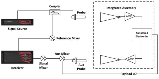
When Figures 2 and 3, and Eq. (1) are taken into consideration, it becomes evident that the test system error is made up of three components: The error resulting from the channel \(\varepsilon _{{\rm c}}\) measurement. DC transformer measurement errors result from the primary current generated by the DC current source fluctuating and the current containing a certain amount of harmonics. This is especially true in the event of a DC system fault, which can cause the current step phenomenon and result in a high number of harmonic components in the current. The error is delayed when the signal is measured by the current transformer and transmitted over long distances via fiber-optic transmission.
Error \(\varepsilon _{{\rm b}}\) resulting from using the standard channel. First and foremost, the accuracy of the current standard’s measurement influences the accuracy of the secondary current \(I_{{\rm b}}\). The magnetic field environment and electromagnetic shielding at the project site also have an impact on the current standard’s measurement accuracy. Furthermore, the accuracy of the high-precision current transformer and the accuracy of the standard resistor are significant contributors to the error of the standard channel, as they also generate harmonic components that contribute to the measurement error of the measured channel. In the standard channel, measurement errors may also result from the current step’s harmonic component.
The internal transformer tester is the source of the errors. This fault consists of the A/D conversion module’s conversion accuracy error, the FPGA’s message parsing error, and the PowerPC’s data analysis and processing error. In order to mitigate the impact of time delay error, the test system is designed with a high-precision synchronization module. Additionally, standard analog, standard digital, and measured digital signals are all precisely time-stamped during the corresponding processing.
The aforementioned error analysis reveals that the accuracy of the DC transformer test system is highly dependent on the conversion accuracy of the tester’s A/D module and the measurement accuracy of the current step caused by a system failure, excluding the error caused by the delay. The corresponding step source is made to test the transient step response of the DC current transformer, and the combination of high-precision A/D acquisition and EMD filtering is used for the A/D module in the tester to increase conversion accuracy.
1) 18-bit high-precision A/D is used to realize signal acquisition in order to address the issue that noise interference and electromagnetic interference produced by the field test environment increase the error of the A/D sampling module. EMD filtering is then applied to the sampled data in order to improve the accuracy of the sampled signal. The following are the precise stages involved in EMD filtering: Initially, ascertain the average value of the upper and lower envelopes using the signal’s highest and minimum value points. \[\label{GrindEQ__4_} m=\frac{v_{1} (t)+v_{2} (t)}{2} , \tag{4}\] where, the upper and lower envelopes are located at \(v_{1} (t),v_{2} (t)\), respectively.
2) As an example, we can represent the difference h between the time-domain sampled data \(s(t)\)and m. \[\label{GrindEQ__5_} s(t)-m=h . \tag{5}\]
3) Steps 1) and 2) should be repeated for each h as a new \(s(t)\) until h satisfies the two requirements of the intrinsic mode function (IMF), which are indicated as follows: \[\label{GrindEQ__6_} c_{1} =h . \tag{6}\]
4) Consider \(c_{1}\)as an IMF, shown by: \[\label{GrindEQ__7_} s(t)-c_{1} =r . \tag{7}\]
As for r, which is the new \(s(t)\), repeat steps 1), 2), and 3) and use the IMF that was later obtained to get, \(c_2,c_{3}\), \(\square\), until r exhibits a monotone trend that stops. \[\label{GrindEQ__8_} s(t)=\sum _{i=1}^{n}c_{i} +r . \tag{8}\]
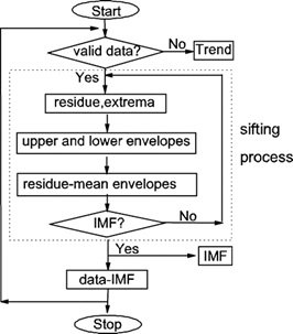
In other words, the initial signal is split into n \(IMFc_{1} ,c_{2} ,\cdots ,c_{n}\) and a residual component r, which is depicted in Figure 4 flowchart. The redundancy of computation is low and computational efficiency is great since the characteristic time scales of each intrinsic mode function in the EMD decomposition result are not provided prior to decomposition, but are instead extracted by the algorithm based on the signal’s properties. Furthermore, the aforementioned decomposition procedure demonstrates that the algorithm is simple to use and appropriate for engineering applications, and the empirical mode decomposition as a whole does not necessitate intricate mathematical computations [17].
A DC system’s DC current experiences a step phenomenon and produces far more harmonic components during faults or disturbances than it does during steady state operation. Therefore, the measurement accuracy of the DC current transformers should be checked independently when the DC transmission system is exposed to such transient processes. In this instance, the test system’s DC power supply needs to be able to replicate the step currents produced by the system’s transient operation. Figure 5 depicts the step source system topology used in this paper.
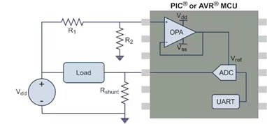
A PowerPC-generated step current digital signal is fed into the step source system. A D/A module then transforms the signal into a tiny analog signal. The D/A module transforms this signal into a small analog signal, which is subsequently transformed into a big analog current by the high-power linear power supply. The signal processing and detecting module, which is an operational amplifier with extremely low zero drift and temperature drift, and the balanced conversion module make up the D/A module. The balancing module has the ability to lower the common mode noise of the operational amplifier caused by interference when there is substantial electromagnetic interference in the power supply. The power conversion module and foil resistor make up the high-power linear power supply. The foil resistors are low-temperature-drift, high-precision current-detecting resistors with weak inductance properties, and the power converter module is a MOS power device. To maintain system safety, the complete step-source system is additionally shielded from thermal overloads.
The subject of the study is the DC current transformer on an extra-high voltage DC transmission line with a bipolar rated power of 10,000 MW, a rated voltage of \(\mathrm{\pm}\)800 kV, a rated current of 6.25 kA, and a total length of 1,234 km. The high-voltage valve is connected to the 500 kV AC system, and the low-voltage valve is connected to the 1,000 kV AC system, working in the inverter state. The transmitting end is in the rectifier state, and the receiving end is a hierarchical structure. Figure 6 displays the structure of the system.

The principal current of the closed-loop test system is the UHV DC transmission line current, and the sampling frequency of the DC current transformer being tested is 50 kHz. The DC current transformer being tested has a 50 kHz sampling frequency. The digital signal that the A/D module converted is then broken down by EMD to produce the waveform that is depicted in Figure 7. Figure 7 shows the original digital signal (i) without EMD decomposition. The DC component (ires) obtained through EMD decomposition has a significantly lower harmonic content than the extracted DC current (i). Of these, the harmonic components, IMF1 \(\mathrm{\sim}\)IMF5, have the highest frequency initially and then decrease gradually as the number of decomposition layers increases. The waveforms in Figure 8 are the same as those in Figures 8 and 9, and they are displayed in Figure 8.

The principal current test’s standard value, 6240A. Ten data tests are first conducted using the standard transformer test system to obtain the current measurement value prior to improvement. Subsequently, ten data tests are conducted using the enhanced transformer test system’s 18-bit high-precision A/D converter module and EMD decomposition to obtain the current measurement value following improvement. Table 1 displays the test results.
| Standard value/A | Before improvement/A | Improved/A |
| 6240 | 6241.32 | 6234.88 |
| 6240 | 6292.35 | 6249.26 |
| 6240 | 6252.38 | 6251.27 |
| 6240 | 6250.57 | 6250.87 |
| 6240 | 6247.54 | 6253.78 |
| 6240 | 6250.18 | 6250.79 |
Table 1 illustrates how the DC current transformer test system produced such a large error in the bad data. To prevent the emergence of large errors in the data, a large number of harmonic components were filtered out through the use of EMD decomposition. The measured values are close to the standard data, even though the system cannot fully meet the standard value.
Using the UHV DC transmission system as an example, Figure 9 depicts the real fault waveform that arises from a short-circuit defect in the DC line with a transition resistance of 0 \(\Omega\). As illustrated in Fig. 9, the maximum current step change that can be managed within 5000 A in the event of a short circuit malfunction in the DC transmission system. To satisfy the amplitude requirements, the step source described in this work may generate a maximum current of 6000 A through the coil fittings.

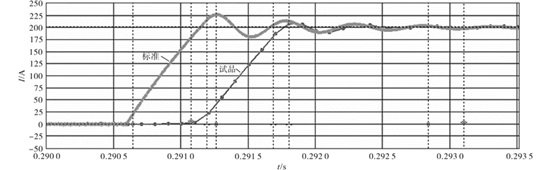
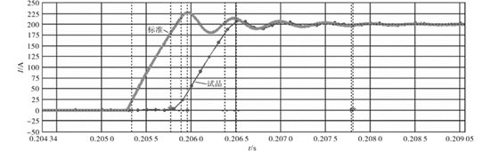
As illustrated in Figure 3, the closed-loop test system is still employed by the DC Current Transformer Step Characterization Test System. The DC current source is a step source, similar to the one depicted in Figure 5, as opposed to the steady state test. To make the step response test easier to employ, a 200 A step current signal is utilized. Figures 9 and 10 display the closed-loop test results for the improved DC current transformers with and without electromagnetic fields (EMD). Table 2 compares and analyses the transient step characteristics of the standard transformer and the DC current transformer under test using the waveform data in Figures 9 and 10.
| Rise time/ \(\mu \)s | Maximum overshoot/% | Transient delay/ \(\mu \) s | ||
| Not EMD | Standard | 416.5 | 13.2 | – |
| Improve | Sample | 495.2 | 2.8 | 76.6 |
| EMD improvement | Standard | 440.2 | 13.2 | – |
| Sample | 489.5 | 3.6 | 50.2 |
Table 2 demonstrates that, in compliance with standard standards, the maximum overshoot is less than 10% and the rise time of the DUT is somewhat longer than that of the standard transformer. The measured transformer has a delay of almost 100 \(\mu\)s when compared to the typical transformer because of factors like transmission distance and data processing requirements. The improved EMD test method offers some technical practicality since, as compared to the traditional source, it does not increase the test transient latency.
This work proposes a DC current transformer on-site closed-loop testing technique based on EMD filtering enhancement, which successfully addresses the harmonic interference and delay error issues with the current testing system. The error resulting from the delay is eliminated with the help of the high-precision synchronization module, which enables the synchronous acquisition of the measured digital quantity and the standard source analog quantity. The 18-bit high-precision A/D acquisition and the addition of the EMD algorithm for the extraction of the DC and current components greatly increase the test system’s measurement accuracy by filtering out a large number of harmonics. Furthermore, a step source system is designed in this study for transient step response testing of DC current transformers, and its viability is demonstrated by tests. To further improve the performance of the DC current transformer test system, future research can investigate new high-precision synchronization approaches and further optimize the development and use of the EMD algorithm.