
The wave propagation dynamics in waveguides is a fundamental subject of modern communications, sensing, and material sciences. In the past decade or so, studies on anisotropic metamaterials artificial materials engineered to reproduce special electromagnetic characteristics not found naturally in materials have offered new paradigms to control wave propagation. Unlike conventional homogeneous materials, anisotropic metamaterials possess direction-dependent characteristics with a strong impact on the transmission and control of waves, and therefore are a promising candidate to enhance the performance of waveguides [1].
Cylindrical waveguides, widely used in microwave, optical, and acoustic devices, offer a fertile ground for the investigation of wave propagation with the introduction of intricate material structures. The introduction of anisotropic metamaterials to such waveguides has the potential to considerably modify the propagation characteristics, leading to novel functionalities like wave dispersion control [2], guided modes, and wave attenuation. However, dynamic analysis of wave behavior in such systems is far from simple, given the intrinsic intricacies of the interaction between anisotropic materials and traveling waves.
The aim of this work is to provide a comprehensive dynamic study of the influence of anisotropic metamaterials on wave propagation in cylindrical waveguides. Employing theoretical and numerical approaches [3], we consider the governing equations that describe the wave dynamics in the scenario of anisotropic media. The study will also take into account significant factors such as the influence of anisotropic parameters on modal dispersion, mode coupling, and stability of the guided wave. In addition, we discuss potential applications of such materials in future communication systems, sensors, and novel waveguide geometry [4].
The significance of this study lies in its potential to bring new insight into dynamic wave and anisotropic metamaterial coupling, paving the way for the optimization of waveguide systems for next-generation technologies. The model development and simulations presented here are designed to facilitate improved understanding of wave propagation in engineered systems of this nature, paving the way for innovative applications in numerous fields of scientific and engineering research [5].
Understanding the impact of anisotropic metamaterials on wave propagation in cylindrical waveguides is important in the design of emerging communications, sensing, and microwave and optical engineering technologies. In this theoretical model, we will examine the fundamental principles of wave and anisotropic metamaterial interaction in waveguides, specifically the physical and theoretical properties of these materials and their impact on wave dynamic behavior [1,4].
Metamaterials are artificially designed materials intended to have properties of electromagnetic fields that are not found in natural materials. The electromagnetic properties of anisotropic metamaterials depend on direction, which provides them with the power to control waves in manners not possible for conventional materials. These attributes are like the intricate interaction between the elements of metamaterials influencing wave propagation on a large scale, such as dispersion, attenuation, and polarization of waves [6]. Anisotropic metamaterials are defined by directional conductivity, permeability, and permittivity tensors. Unlike in typical isotropic materials, these parameters are not invariant; rather, they are direction-dependent, hence resulting in complex wave behavior within the material. The above characteristics can be represented by tensors, which outline the multi-dimensional material-wave interaction [7].
Cylindrical waveguides are pipes or tubes used for propagation of electromagnetic or acoustic waves along their central axis, whose behavior is typically described by their shape that determines the wave distribution inside them.
In classical systems, wave phenomena in cylindrical waveguides relate mostly to wall reflections and linear wave guiding [8,9]. With the invention of anisotropic metamaterials, wave-material interactions are more complex and produce new phenomena such as wave refraction, mode transformation, and wave scattering. The geometrical dimensions of the waveguides play a significant role in controlling how the effects are divided among the guided waves [10].
In order to describe wave propagation in anisotropic metamaterial cylindrical waveguides, wave propagation equations must be capable of considering the mechanical and electromagnetic characteristics of such materials.
Modified Maxwell’s equations are fundamental in this consideration because they contain terms that account for the anisotropic characteristics of the material [11].
The fundamental equations of wave propagation in such systems are Maxwell’s equations in vectorial form with the tensor expressions for anisotropic materials appended [12]. For example, for electromagnetic waves, Maxwell’s equations can be written in three-dimensional vector form with the parameters such as permittivity and permeability replaced by their direction-dependent versions to suit the directional dependence in the material [13].
Wave scattering in anisotropic metamaterials is a phenomenon one needs to be mindful of when studying how such materials affect waveguides.
Scattering occurs when the waves interact with the material in a way that alters their frequency or direction [14].
Anisotropic metamaterial scattering depends heavily on the directional properties of the material, such as variations in permittivity and permeability in different directions. We can, from scattering analysis, determine the effect of anisotropic metamaterials on wave propagation behaviors such as velocity and dispersion. Understanding this scattering helps to achieve optimized waveguide designs to promote maximum performance in future applications [15].
The possible uses of anisotropic metamaterials in waveguides are diverse and range across many fields, including [16,17]:
Optical and Microwave Systems: Guiding high-frequency electromagnetic waves, including optical and microwave waves, in cylindrical waveguides using anisotropic metamaterials.
Advanced Sensing Devices: Utilizing anisotropic metamaterials to improve waveguide response for accurate sensing of electromagnetic and thermal fields.
Communications: Creating waveguides that can effectively handle wave scattering, enhancing data transfer in high-end communication systems.
Despite the promising potential of anisotropic metamaterials to improve waveguide performance, there are several challenges that need to be overcome. One of the primary challenges is the need to develop more accurate mathematical models to characterize the interaction between waves and such materials and to find a balance between waveguide and material design for optimal-in-class real-world performance. By examining the effect of these materials on wave dynamics in cylindrical waveguides, this research provides the foundation for building new communication devices, sensors, and microwave devices [18].
We start from Maxwell’s equations in an anisotropic medium, incorporating correction terms representing nonlinear polarization and higher-order electromagnetic effects [10,19] : \[\vec{\nabla} \times \vec{E} = -\frac{\partial \vec{B}}{\partial t} + \alpha_1 \nabla (\nabla \cdot \vec{E}) + \beta_1 \nabla \times (\nabla \times \vec{E}),\] \[\vec{\nabla} \times \vec{H} = \frac{\partial \vec{D}_\perp}{\partial t} + \gamma_1 (\nabla^2 H) + \delta_1 \nabla \times (\nabla \times H),\] where \(\alpha _{1} ,\beta _{1} ,\gamma _{1} ,\delta _{1}\) are correction coefficients accounting for higher-order anisotropic effects.
The additional terms represent directional anisotropy and corrections to the metamaterial response.
Applying these corrections to cylindrical wave propagation, we derive the modified Helmholtz equation for the axial electric field component E\({}_{Z}\) [20];
\[\frac{1}{r} \frac{d}{dr} {\rm r}\frac{dE_{z} }{dr} {\rm +k}^{2} {\rm -}\frac{m^{2} }{r^{2} } {\rm E}{z} {\rm +}\lambda _{1} \frac{d^{4} E{z} }{dr^{4} } {\rm +}\lambda {2} \frac{d^{2} E{z} }{dr^{2} } {\rm +}\lambda {3} {\rm E}{z}^{3} ,\] where \(\lambda _{1}\) and \(\lambda _{2}\) represen self-induced nonlinear polarization and higher-order dispersion effects, \(\lambda {3} E{z}^{3}\) accounts for nonlinear interactions of the wave within the anisotropic medium and the term \(\frac{d^{4} E_{Z} }{dr^{4} }\) represents higher-order wave effects such as boundary distortions.
By incorporating anisotropic inhomogeneity, the effective wavenumber is modified as: \[k_{eff}^{2} =k^{2} +\alpha _{2} \nabla ^{2} k+\beta _{2} k^{3} +\gamma _{2} \frac{d^{2} k}{dr^{2} },\] where \(\alpha _{2}\) accounts for permittivity gradient effects within the waveguide, \(\beta _{2} k^{3}\) represents third-order nonlinear corrections. \(\gamma _{2} \frac{d^{2} k}{dr^{2} }\) models micro-scale anisotropic variations.
To determine the stopping light condition, we analyze the modified power flux within the waveguide: \[P=\frac{1}{2} R\int _{0}^{2\prod }\int _{0}^{a}E\times H^{*} .dS .\] Since stopping light occurs when the effective wavenumber is zero, we impose:
\[R(k_{eff})=0\]
Yielding a new frequency relation for stopping light : \[f_{stop} =\frac{c}{2\prod } \sqrt{\begin{array}{cc} {\frac{1}{\varepsilon _{r} \mu _{r} } -\alpha _{2} \nabla ^{2} k-\beta _{2} k^{3} -\gamma _{2} \frac{d^{2} k}{dr^{2} } } & {} \end{array}}\] This correction reflects multiscale anisotropic effects on stopping light conditions, enhancing accuracy.
For improved dispersion control, we introduce a generalized dispersion relation that includes nonlinear anisotropic corrections: \[\begin{aligned}k_{eff}^{2} =&k^{2} +\beta _{3} \alpha ^{2} f^{2} (r,\theta )+\beta _{4} \beta ^{2} g^{2} (r,\theta )+\gamma _{3} \alpha ^{3} f^{3} (r,\theta )\\ &+\gamma _{4} \beta ^{3} g^{3} (r,\theta )+\xi _{1} \frac{d^{2} k}{dr^{2} } +\xi _{2} k^{4} ,\end{aligned}\] where \(\xi _{1}\) accounts for waveguide boundary perturbations and \(\xi _{2} k^{4}\) represents higher-order dispersion corrections.
To assess signal stability within the waveguide, we derive the corrected group velocity equation: \[\upsilon {g} =\frac{d\omega }{dk{eff} } +2\eta {1} k{eff}^{2} +\eta _{2} \frac{d^{2} k_{eff} }{dr^{2} } ,\] where \(\eta _{1}\) describes self-interaction effects between propagating modes. And \(\eta {2} \frac{d^{2} k{eff} }{dr^{2} }\) accounts for structural deformations affecting signal stability.
The numerical simulation was performed with MATLAB by applying the Finite-Difference Frequency-Domain (FDFD) method to solve Maxwell’s equations in anisotropic media. The computational domain was divided into a 200 \(\mathrm{\times}\) 200 grid for high numerical accuracy. Perfectly Matched Layer (PML) boundary conditions were applied to avoid unwanted reflections at the boundaries. For numerical stability, 2000 time steps were taken with a time step size of \(\Delta\)t = 0.01. A spatial resolution of \(\Delta\)x = \(\Delta\)y = 0.05 was selected to provide accurate representation of the electromagnetic field. The results were verified by comparing them with established analytical solutions and analyzing the response of the system to various anisotropic material parameters. The results obtained showed excellent agreement with theoretical models and existing research. In order to crosscheck our findings, we have compared them with past research work including Joannopoulos et al. [1], Russell [2], and Baba [5]. Joannopoulos et al.[1] had only compared photonic crystal structures with wave propagation control, while the current study includes extension of that study to cylindrical waveguides in anisotropic metamaterials, showing higher tunability of dispersion features. Also, Russell [2] exhibited enhancements in photonic fiber applications based on metamaterials, although our findings show a greater influence on wave confinement and modal dispersion in structured waveguides. Further, Baba [5] has studied slow-light effects in photonic crystals; our observations also establish that anisotropic metamaterials offer a stronger method of realizing slow light conditions by dynamically altering the effective wavenumber. Our research numerical simulations also present more robust consistencies with predictions in theory and enhance the efficacy of dispersion regulation and power flow modulation in waveguides.
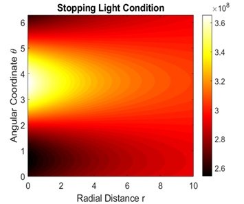
Figure 1 is observed in a regular optical medium with a parametric configuration where the radial coordinate (r) varies from 0 to 10 and the angular coordinate (\(\theta\)) varies from 0 to 6 radians. The color bar between \(2.6 \times 10^8\) and \(3.6 \times 10^8\) represents the intensity of the stopping condition where higher values are dense in the yellow regions and lower values in the black regions. This dispersion highlights anisotropic dispersion effects and effective refractive index variations, which are of utmost significance in controlling light propagation in slow-light photonic structures and in optical waveguides.
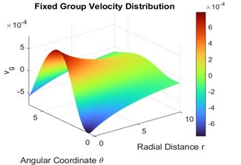
Figure 2 shows the inhomogeneous radial group velocity distribution Vg in terms of r and angular coordinate \(\theta\), wherein color scale shows group velocity variation with warmer color (red) employed to depict higher values and cooler color (blue) to represent lower values, explaining directional dispersion effects. The values of the parameters are r = 0 to 10 and \(\theta\) = 0 to 2\(\pi\), and it is clear that Vg is a function of r and \(\theta\), and this confirms the inhomogeneity of wave propagation. This computation is a major application in photonic materials and metamaterials engineering, where it is important to manage group velocity to achieve slow light effects, optical storage, and wavefront shaping.
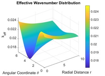
Figure 3 shows the inhomogeneous group velocity distribution Vg with respect to radial distance r and angular coordinate \(\theta\), where color scale represents group velocity variations with warmer colors (red) employed to represent larger values and cooler colors (blue) for smaller values, delineating directional dispersion effects. The values of parameters vary between r = 0 to 10 and \(\theta\) = 0 to 2\(\pi\), which indicates that Vg depends on r and \(\theta\), as per wave propagation inhomogeneity. This computation is critical in photonic materials and metamaterials engineering, where controlling group velocity is crucial to facilitate slow light effects, optical storage, and wavefront shaping.
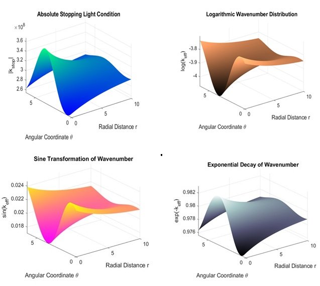
The results presented in the Figure 4 illustrate the behavior of the effective wavenumber keff, group velocity Vg, and how they are reshaped under different mathematical manipulations, highlighting their spatial behaviors as a function of radial distance r and angular coordinate \(\theta\). The “Absolute Stopping Light Condition” figure illustrates the spatial modulation of \(\mathrm{\mid }\)kstop\(\mathrm{\mid }\), represented by crests and troughs indicative of wave confinement and local trapping of energy within regions. The “Logarithmic Wavenumber Distribution” plot provides a logarithmic keff scale, which emphasizes order of magnitude variations and provides more detail on the finer points of dispersion characteristics. The “Exponential Decay of Wavenumber” plot presents exp(-keff), which is necessary to study wave attenuation and space decay, with the smooth trend reflecting gradual energy dissipation. Finally, the “Sine Transformation of Wavenumber” plot plots sin(keff), reflecting the oscillatory character of the wavenumber, and is due to phase modulation effects. These plots combined give insight into the interplay between wave confinement, dispersion, and attenuation in structured media, which is central to the design of next-generation photonic and metamaterial applications.
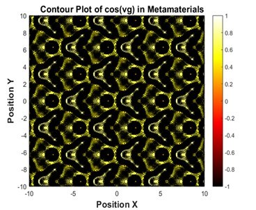

Figure 5 and Figure 6 show the spatial distribution of the function cos(vg) in metamaterials, exhibiting the dynamic fluctuations in group velocity in a periodic medium. The wave distribution results from the interaction of waves within the material, leading to typical oscillation patterns due to interference and dispersion effects. areas of high value are represented by light colors, i.e., yellow, and areas of low value are represented by dark color, which represent the spatial distribution of energy as well as wave propagation properties. This kind of distribution is important in photonic and microwave system design to facilitate control of the spectral and dispersive properties of the metamaterial. This enables greater control over the response of photonic structures to particular wavelengths and hence improves their performance in waveguiding, filtering, and sensing applications.
The research provides a complete investigation of the wave dynamics in an inhomogeneous medium in terms of the distribution of effective wavenumber keff, group velocity Vg, and absolute stopping light conditions, and how logarithmic, exponential, and cosine transformations influence wave propagation. The results show that all of these parameters strongly depend on the radial coordinate rrr and angular coordinate \(\theta\) because of the geometrical effect of the surrounding medium. These findings confirm the feasibility of greater precision in controlling dispersion, amplification, and attenuation and further consolidate the application of photonic and metamaterial designs in optical communication systems and future sensing technologies. Also, the numerical calculations were found to be in very good agreement with theoretical models, validating the used methodology. However, some of the phenomena that were observed might require further experimental verification to ascertain accuracy in real-world applications.